
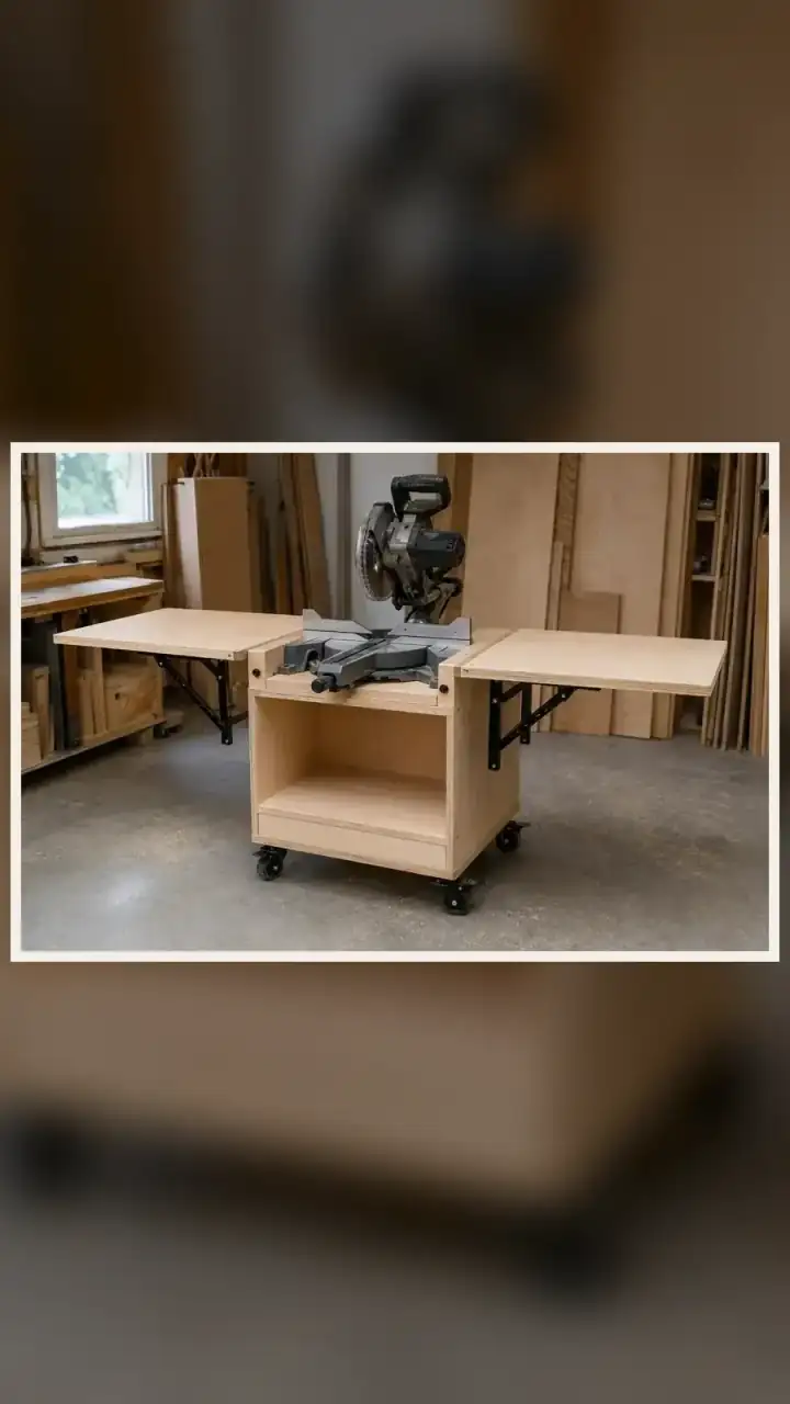
A miter saw needs more than a flat place to sit. Long boards require support at exactly the same height as the saw table, the machine needs enough clearance to bevel and slide, and the entire setup must remain stable while a cut is made. These mobile miter saw stand plans solve those problems with a compact rolling cabinet, two 27-inch folding wings and an adjustable recessed saw deck.
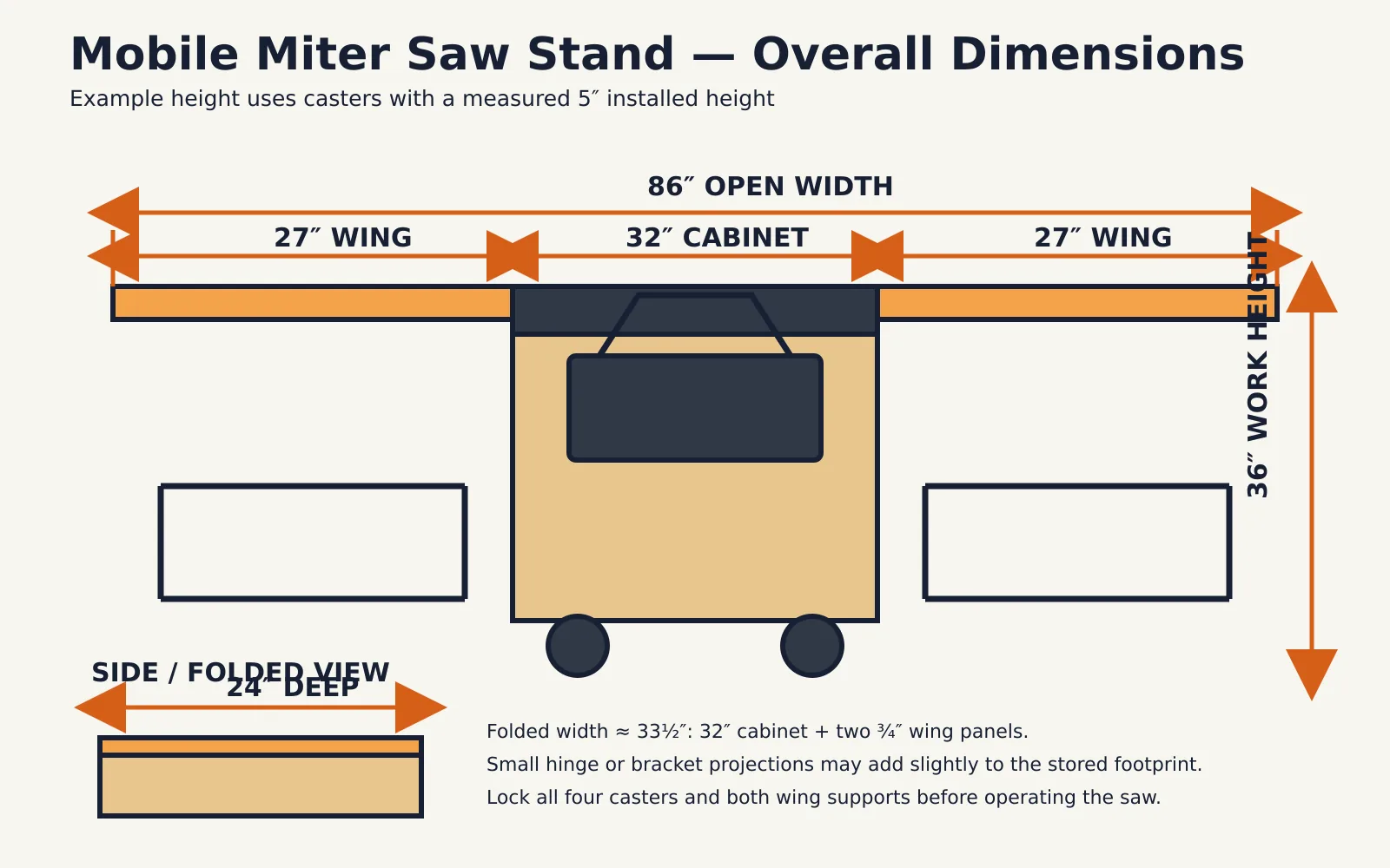
With both wings open, the stand is 86 inches wide, 24 inches deep and 36 inches high when built with casters that measure 5 inches from the floor to the mounting plate. Fold the wings down and the main cabinet occupies only 32 inches of width; the folded panels increase the maximum width to approximately 33½ inches, excluding small hinge or bracket projections.
The important feature is not one universal saw-platform height. Miter saws have different base sizes, table heights and slide clearances, so this plan shows you how to measure your actual machine and position the deck accurately. If you are comparing other layouts first, browse these 15 miter saw station plans for small workshops.
Power-tool safety: This project is general DIY information, not a replacement for the manual supplied with your saw, casters, hinges or folding brackets. Bosch’s current miter-saw guidance requires a level, firm work surface and adequate support for stock that extends beyond the saw table. Follow the requirements for your exact machine, keep every guard and control unobstructed, disconnect power before mounting or adjusting the saw, and use appropriate eye, hearing and respiratory protection. Do not use the stand until the casters are locked, the wings are fully supported and the saw is securely mounted.
Mobile Miter Saw Stand Plan at a Glance
| Main cabinet | 32″ W × 24″ D |
|---|---|
| Work-surface height | 36″ with casters that have a measured 5″ installed height |
| Open width | 86″ |
| Each folding wing | 27″ W × 24″ D × ¾″ thick |
| Folded maximum width | Approximately 33½″, plus minor hardware projections |
| Adjustable saw deck | 27½″ W × 19″ D |
| Lower shelf | 30½″ W × 22″ D |
| Difficulty | Intermediate |
| Build time | One weekend, plus finish-curing time |
| Estimated material cost | Approximately $180–$320 USD, depending on plywood and hardware |
Measure Your Saw and Casters Before Cutting
Do not cut the cabinet simply because the dimensions fit the saw in a photograph. Place your unplugged saw on a flat surface and record five measurements:
- Maximum base width: Include feet, mounting tabs and any handle that remains outside the cabinet.
- Maximum base depth: Include the front miter handle and everything behind the fence.
- Saw-table height: Measure vertically from the surface beneath the saw’s feet to the flat table that supports the workpiece.
- Full operating envelope: Move the unplugged head through every intended miter, bevel and sliding position. Include dust-hose clearance.
- Mounting-hole locations: Measure the manufacturer-provided mounting points, not convenient holes in a plastic cover.
This plan provides a clear saw-deck area approximately 27½ inches wide by 19 inches deep. If your mounting footprint is larger, widen or deepen the cabinet before cutting any plywood. Never position a fence, wing, bolt or dust hood where it can interfere with the blade, guard, slide rails, bevel mechanism or power controls.
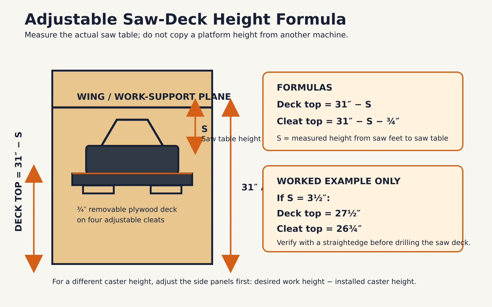
Measure the installed caster height as well. The plan’s 31-inch side panels assume the casters measure exactly 5 inches from the floor to the underside of the cabinet. For a different caster, use this formula:
Side-panel height = desired work-surface height − installed caster height
For example, 36″ − 5″ = 31″. If your casters measure 4¾ inches, cut the side panels 31¼ inches high to retain a 36-inch wing surface.
How to Calculate the Adjustable Saw-Deck Height
The upper surface of each wing must be flush with the table of the installed saw. Let S equal the measured height from the saw’s feet to its work table. The wing surface is 31 inches above the cabinet bottom when the side panels are 31 inches tall. Therefore:
Saw-deck top above cabinet bottom = 31″ − S
The deck is ¾-inch plywood and rests on cleats, so:
Cleat-top height above cabinet bottom = 31″ − S − ¾″
If the saw table is 3½ inches above its feet, the deck top belongs 27½ inches above the cabinet bottom and the cleat tops belong at 26¾ inches. Treat this only as an example—use the measurement from your machine.
Materials and Hardware
- One 4′ × 8′ sheet of ¾″ cabinet-grade plywood
- One half-sheet of ½″ plywood for the shelf and lower back
- One 8′ 2×4 for the upper rail and optional lower blocking
- One 8′ 2×6, cut into four reinforcement blocks
- One 8′ 2×2 or straight stock ripped to 1½″ square for deck cleats
- One 8′ 1×2 for lower-shelf cleats
- Two 24″ continuous or piano hinges suitable for the wing assembly
- Four heavy-duty locking folding shelf brackets—two per wing—selected for the intended span and load
- Four locking swivel casters with suitable mounting hardware and a verified installed height
- Manufacturer-approved bolts, washers and locknuts for mounting the miter saw
- 1¼″ coarse-thread pocket-hole screws for ¾″ plywood, or equivalent cabinet screws
- 2½″ structural wood screws for rails and reinforcement blocks
- ¾″ or 1″ screws for attaching the ½″ back and shelf where appropriate
- Wood glue
- Optional iron-on edge banding
- Paint or a durable clear finish
- Optional removable power strip mounted away from dust and moving parts
Do not choose brackets or casters from appearance alone. Review each manufacturer’s mounting pattern, material-thickness requirement, hardware, load conditions and locking procedure. Hardware capacities do not automatically become the safe capacity of the finished stand.
Tools You Will Need
- Track saw or circular saw with a straightedge guide
- Miter saw or circular saw for construction-lumber parts
- Drill/driver and suitable bits
- Pocket-hole jig, optional
- Combination square and framing square
- Long straightedge or level
- Clamps
- Random-orbit sander
- Wrenches or sockets for caster, bracket and saw hardware
- Eye, hearing and respiratory protection
A clear floor and predictable material path make this project much easier. If the garage is already crowded, review this guide to setting up a small woodworking shop before deciding where the open wings and long boards will travel.
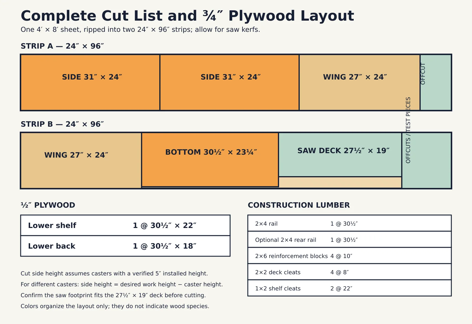
Complete Cut List
¾-Inch Plywood
| Part | Qty. | Cut size | Notes |
|---|---|---|---|
| Cabinet sides | 2 | 31″ × 24″ | Assumes 5″ installed caster height |
| Folding wings | 2 | 27″ × 24″ | Best faces upward |
| Cabinet bottom | 1 | 30½″ × 23¼″ | Fits between sides |
| Adjustable saw deck | 1 | 27½″ × 19″ | Fits between inner reinforcement blocks |
½-Inch Plywood
| Part | Qty. | Cut size | Notes |
|---|---|---|---|
| Lower shelf | 1 | 30½″ × 22″ | Leaves rear clearance |
| Lower back | 1 | 30½″ × 18″ | Fits between sides; upper cabinet remains open |
Construction Lumber
| Part | Qty. | Cut size | Material |
|---|---|---|---|
| Upper front rail | 1 | 30½″ | 2×4 |
| Optional lower rear rail | 1 | 30½″ | 2×4 |
| Wing-bracket reinforcement blocks | 4 | 10″ | 2×6 |
| Adjustable deck cleats | 4 | 8″ | 2×2 |
| Lower-shelf side cleats | 2 | 22″ | 1×2 |
Folding-Wing Hardware Layout
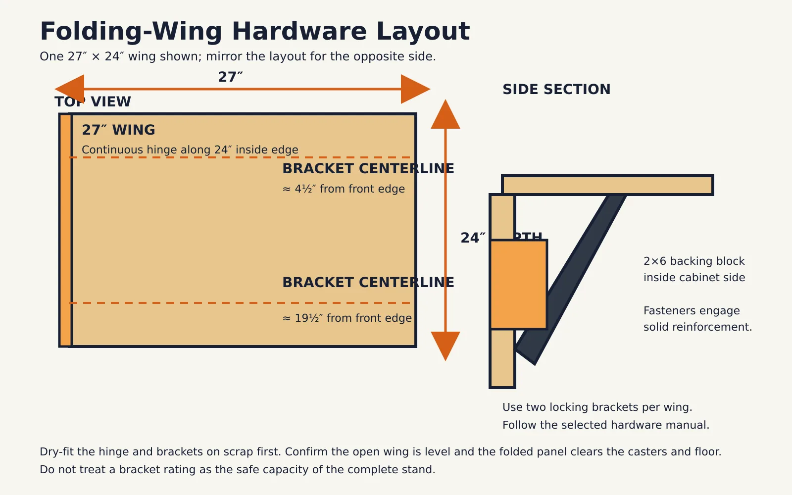
Each 27″ × 24″ wing connects to the cabinet along its 24-inch inside edge. Position the continuous hinge so the open wing surface aligns with the top edge of the cabinet side. The exact hinge orientation depends on the selected product; dry-fit it with scrap first and follow its installation instructions.
Install two locking brackets beneath each wing. The diagram places their centerlines approximately 4½ inches and 19½ inches from the front edge. That spreads the support across the 24-inch depth while leaving room for the saw area. Reinforce the cabinet side behind every bracket with the 10-inch 2×6 blocks. Adjust the locations only when the bracket instructions or your saw clearance require it.
How to Build a Mobile Miter Saw Stand With Folding Wings
Step 1: Measure the Saw, Hardware and Working Space
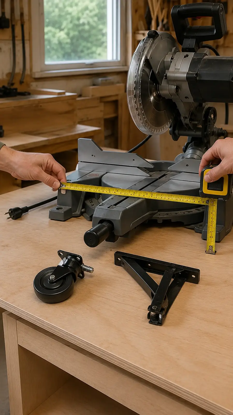
Unplug the saw and record the five machine measurements listed earlier. Lock the head for transport only as the manual directs, then measure the stationary base. Afterward, move the unplugged machine through its full operating range to understand the required space.
Measure the casters from the floor to their mounting plates under a realistic load, and inspect the hinges and bracket instructions. Mark the intended stand location on the floor with painter’s tape. Open an imaginary 86-inch support span and confirm that a long board will not cross a doorway, vehicle path or busy aisle.
Step 2: Break Down and Label the Plywood
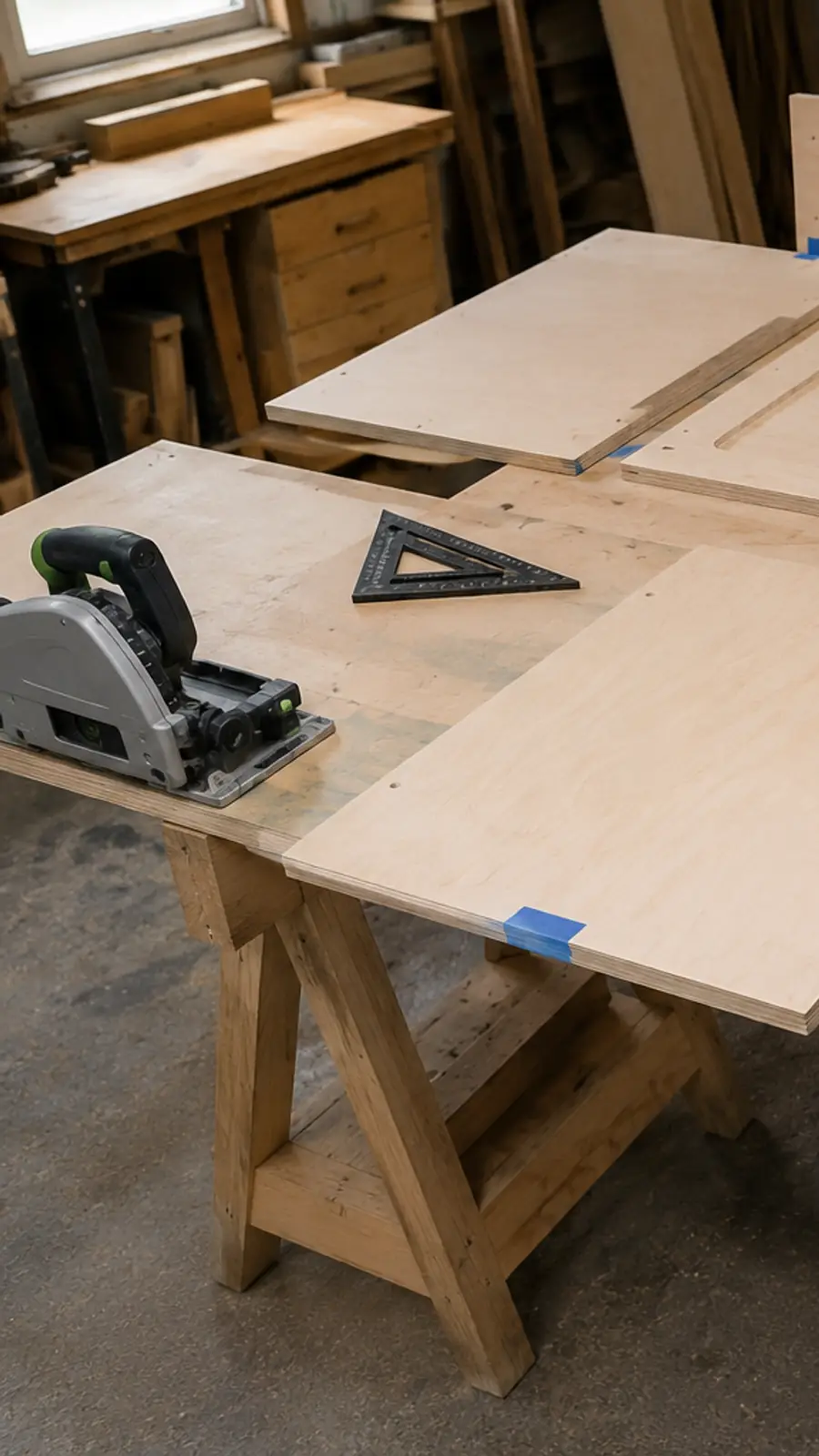
Trim one factory edge to create a reliable reference, then rip the ¾-inch sheet into two 24-inch-wide strips. Crosscut the parts according to the cut diagram, allowing for saw kerfs. Cut the ½-inch shelf and lower back separately.
Label the interior faces, front edges and best veneer faces. Pair the two side panels and check that they are identical. Pair the wings and square their corners. A difference of even ⅛ inch can make the open surfaces difficult to align.
Step 3: Assemble the Cabinet Shell
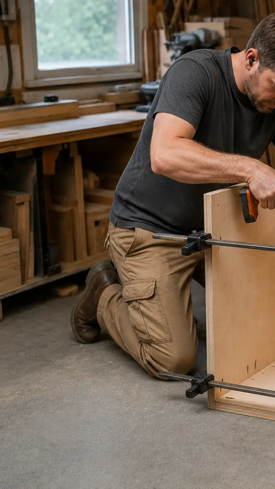
Position the 30½″ × 23¼″ bottom between the two side panels with its front edge flush and its lower face flush with the side bottoms. Join it with glue and pocket screws on concealed faces, or countersunk cabinet screws through the sides.
Install the 30½-inch upper front rail between the sides. Keep it low enough that it cannot interfere with the saw platform or front controls. Compare the cabinet diagonals and adjust the clamps until they match. The outer width should be exactly 32 inches.
Step 4: Add Bracket Reinforcement and the Lower Back
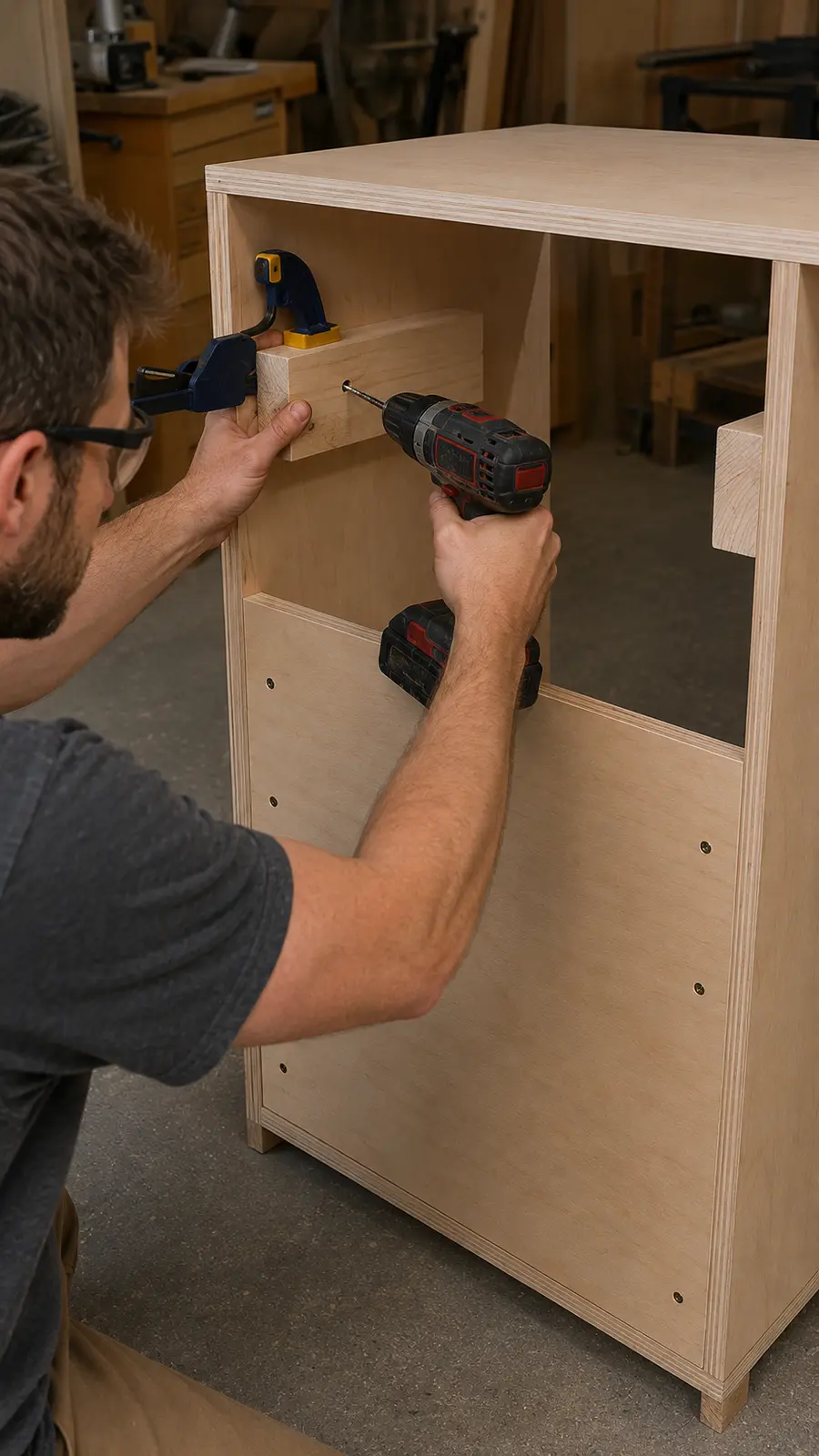
Mark the future folding-bracket positions on both side panels. Fit two 10-inch 2×6 reinforcement blocks against the inside of each side, directly behind those zones. Glue and secure the blocks with suitable structural screws while preserving the 27½-inch clear width for the saw deck.
Install the 30½″ × 18″ lower back between the sides. Keep the upper cabinet open so the saw, dust port and slide mechanism have room. Square the cabinet again before tightening every fastener.
Step 5: Install the Lower Shelf
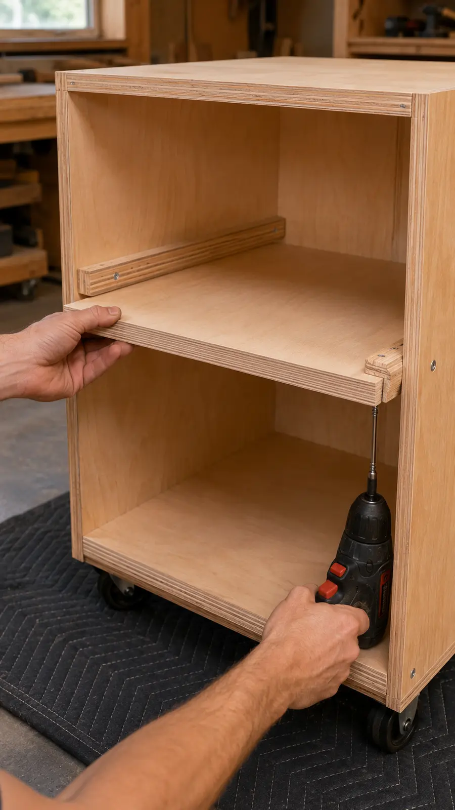
Mark a consistent shelf elevation—approximately 6 inches above the cabinet bottom works for many storage layouts. Attach the two 22-inch 1×2 cleats level on the inner side panels, then place the ½-inch shelf on them.
Fasten the shelf without driving screws through the outer faces. Store heavier accessories on the lowest available level and keep dust hoses, electrical connections and caster locks accessible. For more storage around the station, pair this build with these French cleat tool holders rather than overloading the cart.
Step 6: Mount and Lock the Casters
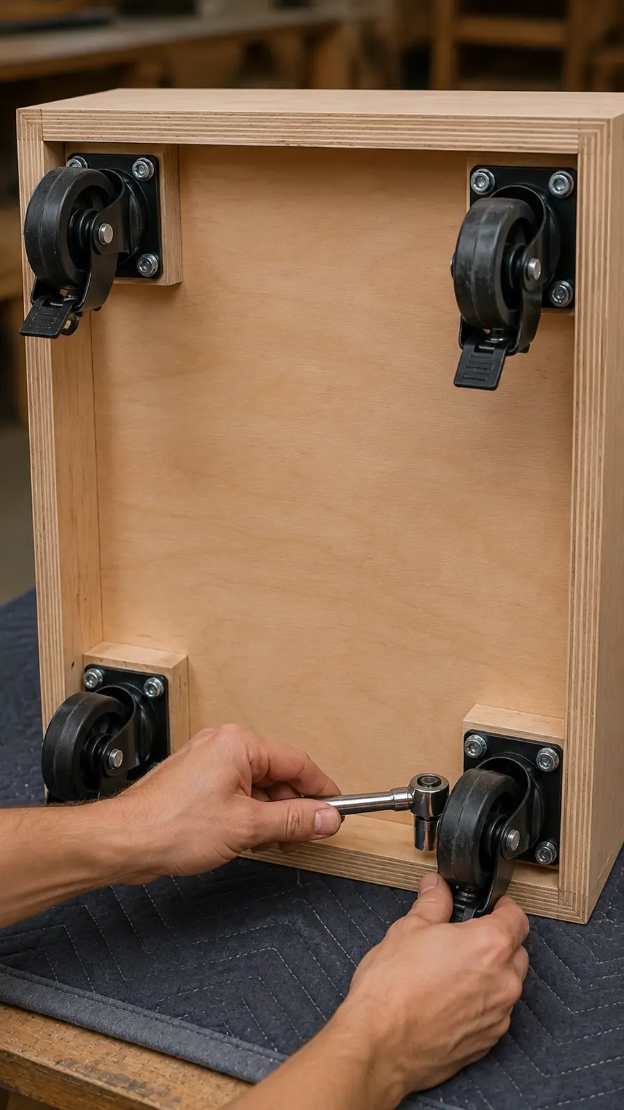
Turn the empty cabinet upside down on a protected surface. Lay out the caster plates near the corners while maintaining adequate edge distance. Reinforce the mounting zones if the caster manufacturer requires thicker material.
Drill clean holes and use the specified bolts, washers and locknuts or approved structural fasteners. Return the cabinet upright, engage all locks and push gently from several directions. The cart should not rock, rack or roll.
Step 7: Calculate and Install the Adjustable Saw Deck
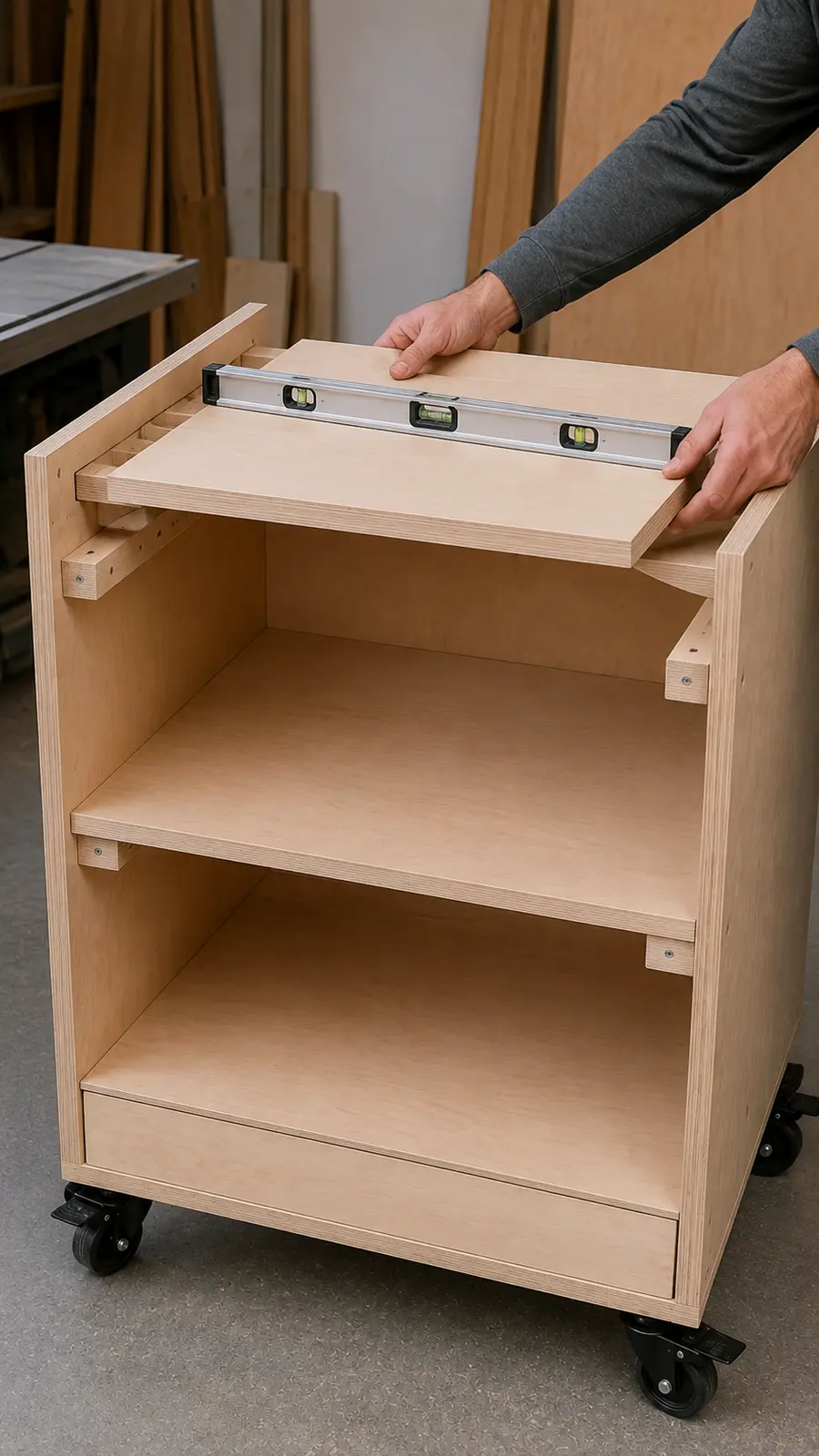
Use your recorded value for S. Mark the calculated cleat-top height on all four reinforcement zones and transfer it with a level. Attach the four 8-inch 2×2 cleats so their upper edges share one plane.
Place the 27½″ × 19″ deck on the cleats without glue. Set the unplugged saw on it and lay a straightedge across the saw table toward each future wing. The straightedge should meet the cabinet-side top line exactly. Shim temporarily if needed, then correct the cleat positions. Keeping the deck removable makes future saw changes possible.
Step 8: Secure the Miter Saw and Test Its Full Movement
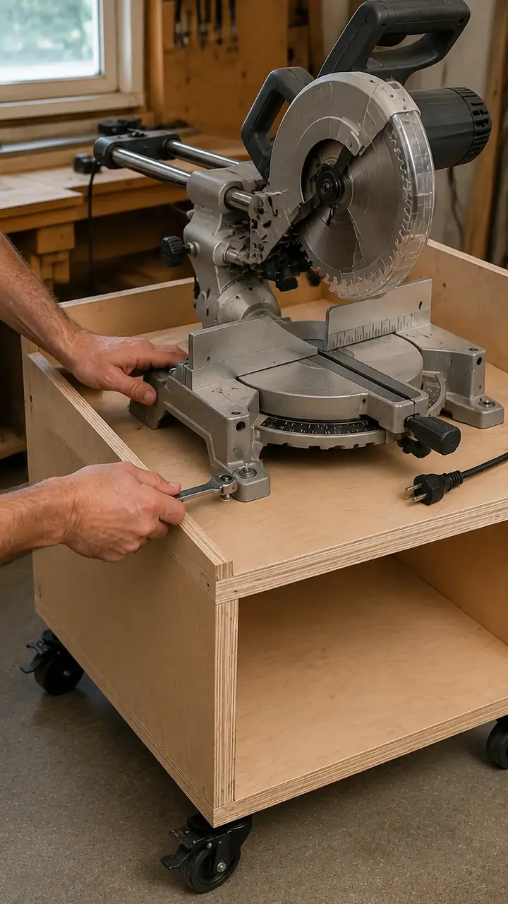
Mark the manufacturer-provided mounting holes on the deck. Remove the machine, drill the holes and reinstall it with suitable bolts, large washers and locknuts. Do not rely on short screws driven only into plywood unless the saw manufacturer expressly permits that method.
With the machine still unplugged, test the full miter, bevel and slide range. Confirm that the cord, dust connection, rails, handles and clamps remain clear. The Bosch operating guidance specifically emphasizes a firm, level mounting surface and adequate support for long or wide stock; the wings will provide that support only after they are correctly installed and aligned.
Step 9: Attach the Two Continuous Hinges and Wings
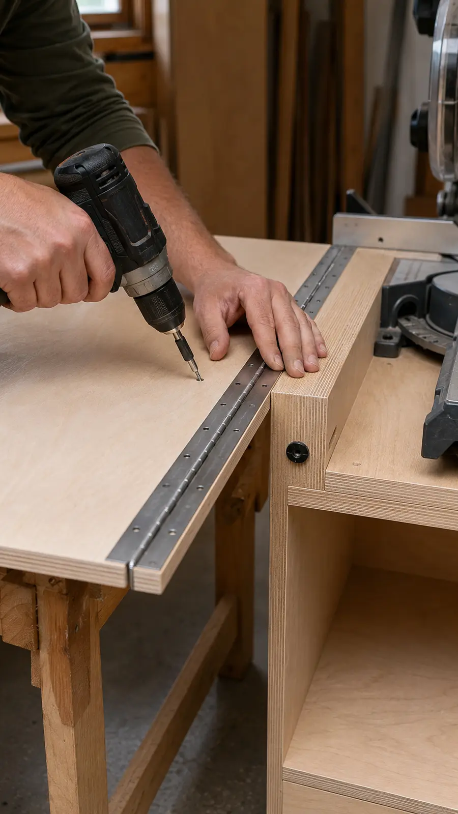
Support one wing at the exact cabinet-top height with a temporary table or blocks. Leave the manufacturer-specified hinge gap and clamp the wing so its 24-inch edge remains parallel to the side panel.
Predrill every required hole. Fasten the hinge with the supplied hardware or approved replacements long enough to engage the reinforced structure without penetrating unsafe areas. Repeat for the opposite wing. Fold each panel slowly and confirm that it clears the casters, floor and cabinet.
Step 10: Install and Test the Locking Folding Brackets
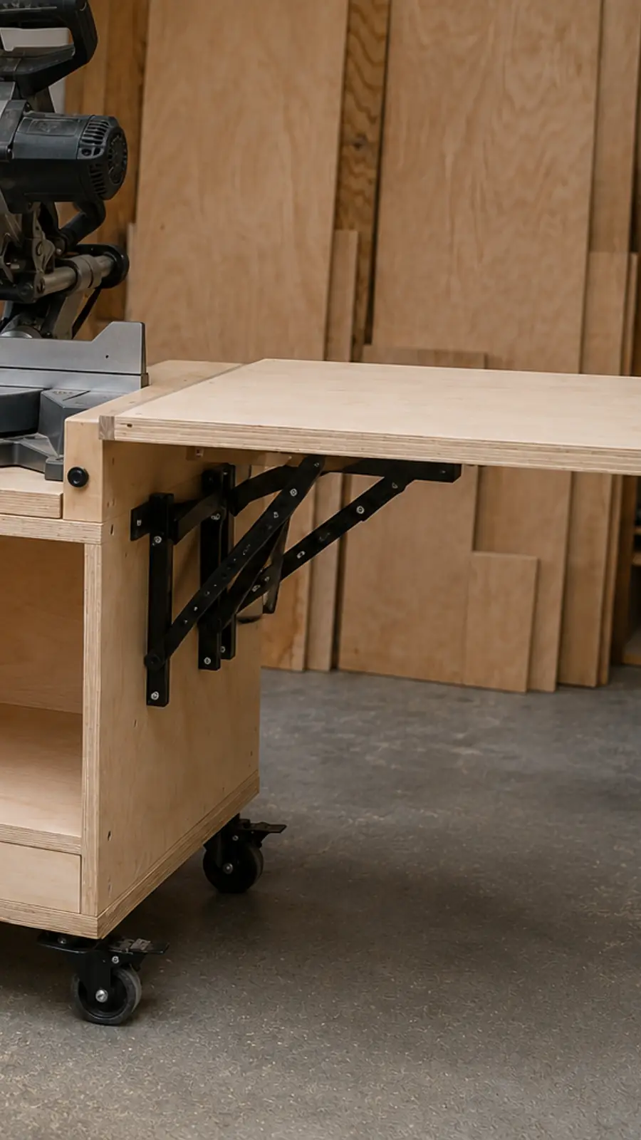
Mark the bracket centerlines about 4½ inches and 19½ inches from the wing’s front edge, or use the locations required by your selected hardware. Hold each bracket fully open, square it to the hinge and mark the holes.
Predrill and fasten through the cabinet side into the 2×6 reinforcement. Follow the bracket maker’s instructions for fastener diameter, engagement and locking clearance. Open and close each bracket several times without a load. Both locks must engage positively, and the wing must not sag or twist.
Step 11: Align and Load-Test the Support Surfaces
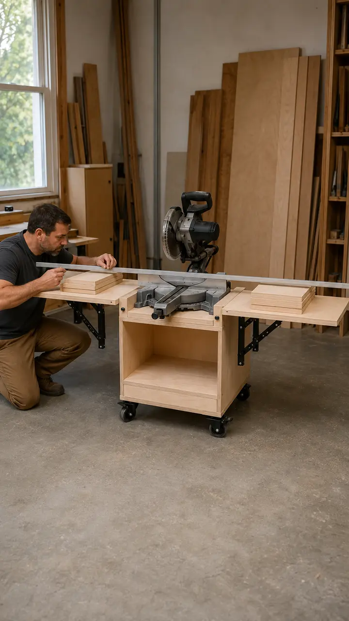
Lock all four casters on a level floor and open both wings until every bracket locks. Lay a long, known-straight board or level across the left wing, saw table and right wing. Check near the front and rear.
Correct small differences with durable shims at the bracket or hinge locations only when the hardware instructions permit it. Do not use loose scraps that can fall out. Gradually test the wings with inert weight well below the hardware ratings while watching the hinges, fasteners, cabinet sides and casters. This plan does not publish an untested weight capacity.
Step 12: Sand, Finish and Organize the Station
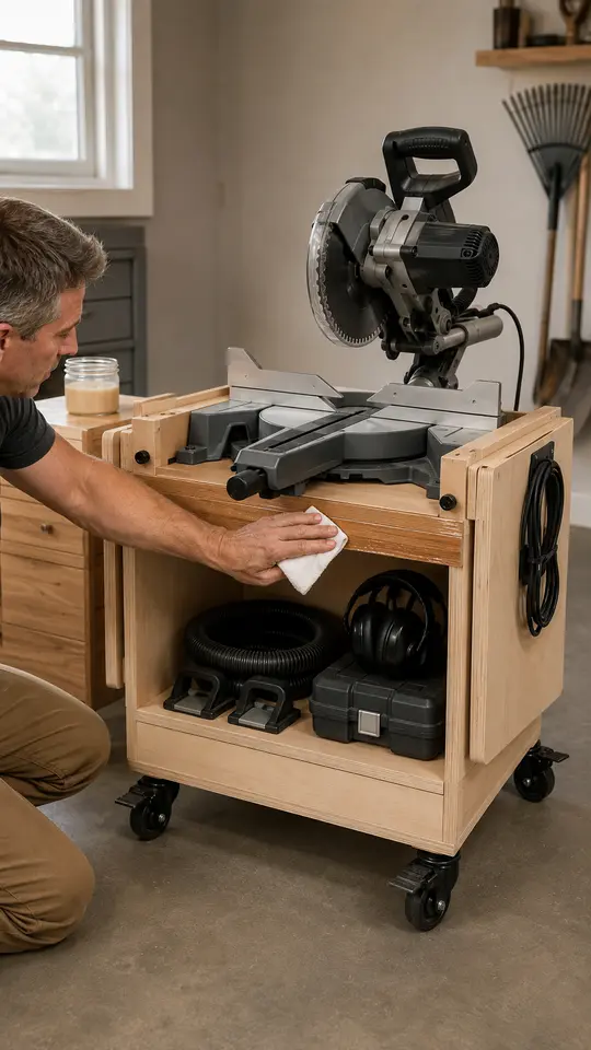
Remove the saw and hardware as needed before sanding. Ease the plywood edges, apply optional edge banding and finish every exposed face according to the coating manufacturer’s preparation, ventilation and cure requirements. Do not allow finish buildup to change the hinge gap or deck alignment.
Reassemble the stand, route the unplugged cord and dust hose away from the brackets and casters, then repeat the movement and alignment checks. These wood finishing tools for beginners can help you prepare a cleaner surface.
Want a Better-Organized Small Workshop?
Disclosure: This section contains an affiliate link. If you purchase through it, Bubblerelief may earn a commission at no additional cost to you.
A folding miter saw stand solves one machine’s storage and stock-support problem. It cannot decide where the table saw belongs, how lumber should travel through the room, which tools deserve permanent floor space or how dust collection and lighting should fit together.
If you are reorganizing the entire garage, The Ultimate Small Shop is an optional workshop-planning resource to review. It focuses on arranging a functional woodworking space on a limited footprint and budget. Review the current offer, examples and terms carefully; the free stand plan above may be all you need if the miter saw is your only layout problem.
See the current Ultimate Small Shop offer →
Useful Optional Upgrades
Add Removable Wing Fences
Short removable fences can help support straight stock, but they must align with the saw fence and remain outside every miter and bevel path. Kreg’s track-and-stop guidance uses support boxes matched to the saw-table height and a fence above the work surface. Treat any fence as a separate, machine-specific upgrade rather than attaching one automatically.
Add a Stop Track
A stop improves repeated cuts when installed and calibrated correctly. Use a commercial system according to its manual, and confirm that the stop can move or swing out of the way when it is not appropriate for the cut.
Add Dust Collection Carefully
A compact vacuum can fit on the lower shelf, but a hood must preserve the saw’s full slide and bevel envelope. Use flexible hose with enough slack for movement and strain relief that keeps it out of the folding hardware. The power-tool organizer with charging station offers additional storage ideas for batteries and accessories away from the saw.
Coordinate the Stand With Other Mobile Tools
Keeping several rolling surfaces at a shared height can create temporary assembly support. Compare the design with these table saw workbench plans and the measured DIY router table plan. Never use a neighboring tool as stock support unless it is stable, aligned and safely positioned.
Common Miter Saw Stand Mistakes
- Copying another saw’s deck height: Measure from your saw’s feet to its own work table.
- Ignoring slide and bevel clearance: Test the entire unplugged operating envelope, not only the 90-degree position.
- Mounting brackets into ¾-inch plywood alone: Use substantial backing and the hardware manufacturer’s specified fasteners.
- Using only two locking casters: All four casters on this plan should lock, and every lock should engage before a cut.
- Aligning only the front edge: Check both wings near the front and rear with a long straightedge.
- Trusting a hardware rating as a stand rating: The plywood, joints, hinges, fasteners, casters and workmanship all affect the assembly.
- Adding a continuous fence without clearance checks: A fence can interfere with miter, bevel, guard or clamp movement.
- Rolling the cart with wings open: Fold and secure the wings, lock the saw for transport as its manual directs, and clear the route first.
- Letting storage block the controls: Keep caster locks, the power disconnect and dust connections accessible.
Frequently Asked Questions
Will these mobile miter saw stand plans fit every saw?
No universal cabinet fits every miter saw. This stand accepts a machine whose mounting footprint and operating envelope fit the available deck and open upper cabinet. Measure first and enlarge the cart when necessary.
Why is the saw deck only 27½ inches wide inside a 32-inch cabinet?
The side panels use ¾ inch each, and the 2×6 reinforcement blocks project 1½ inches into the cabinet on each side. That leaves 32″ − 1½″ − 3″ = 27½″ of clear deck width.
How tall should a mobile miter saw stand be?
This example uses a 36-inch work surface, but comfort and safe control matter more than copying one height. Choose the desired surface height first, subtract the installed caster height and adjust the side-panel cut. The saw deck is then calculated separately so the saw table meets the wings.
Can I use MDF for the wings?
Use the material specified by the selected hinge and bracket system. MDF is flat but heavy and holds some fasteners less reliably near edges. Cabinet-grade plywood is the more practical choice for these moving panels.
Can the wings support eight-foot boards?
The 86-inch open span supports material farther from the saw than the machine table alone, but very long or heavy stock may still need an independent roller stand or additional support. Follow the saw manual and support the work so neither the stock nor cutoff can tip.
Should I add a power strip?
A removable, appropriately rated shop power strip may be convenient, but it must not replace a suitable electrical circuit or required dust-control practices. Keep it away from dust accumulation, moving hardware and wheel paths. Use a qualified electrician when the circuit or wiring is uncertain.
Can I build the stand without casters?
Yes. Remove the casters and lengthen the side panels to retain the intended work height, or build a fixed base. A stationary cabinet can be simpler and more rigid when the saw has a permanent location.
What should I build next for the workshop?
Organize sheet goods and boards with these lumber storage rack plans, add accessible wall storage with the French cleat projects linked above, or create a compact assembly area using this folding wall-mounted workbench plan.
Final Thoughts
A useful miter saw stand does not need a wall of drawers. It needs a stable cabinet, secure machine mounting, flush stock support, reliable wing hardware and enough clearance for the saw to operate exactly as its manufacturer intended.
Build around the actual machine rather than the photograph: measure the saw and casters, recalculate the side and deck heights, reinforce the bracket zones, align both wings with a straightedge and test the empty mechanism before adding load. Those checks turn a compact rolling cabinet into a genuinely practical part of a small workshop.