
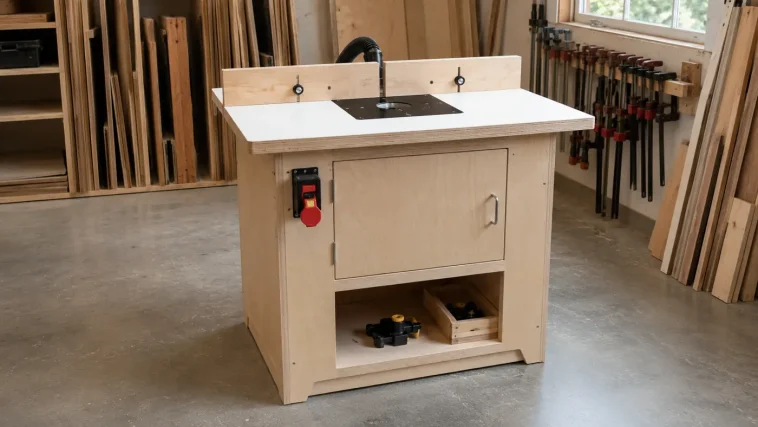
If you are new to this tool, read the complete beginner’s guide to using a wood router first. A router table changes the position of the machine and the correct feed direction, but it does not replace the instructions, guards or limitations supplied by the router, plate, bit, switch and dust-extraction manufacturers.
DIY Router Table Plan at a Glance
| Finished size | Approximately 32″ W × 24″ D × 36″ H |
|---|---|
| Cabinet footprint | 30″ W × 22″ D |
| Tabletop | Two layers of ¾″ MDF, 32″ × 24″ |
| Insert plate | Nominal 9¼″ × 11¾″ × ⅜″; verify yours |
| Difficulty | Confident beginner to intermediate |
| Build time | One weekend, plus finish-curing time |
| Best features | Flat top, enclosed router bay, dust port, split fence and lower storage |
Important Safety and Compatibility Notes
A router bit may spin at tens of thousands of revolutions per minute. Treat the table as a power-tool station, not as ordinary furniture. Disconnect the router from power before changing bits, moving the fence, adjusting the plate, opening the router compartment or performing maintenance. Wear eye and hearing protection and use respiratory protection suitable for the dust produced.
- Use only a router that its manufacturer permits to be mounted in a table.
- Mount the router with the hardware and hole pattern specified for that model.
- Use a commercial paddle-style router-table switch rated for the router’s electrical load. Do not fabricate wiring or install an ordinary household switch inside the wooden cabinet.
- Keep the insert plate perfectly supported and flush with the tabletop.
- Use the smallest compatible insert ring around the bit and retain an appropriate bit guard.
- Feed stock against the cutter rotation. With the fence behind the bit, normal router-table feed is usually from right to left. Kreg also emphasizes feeding against the cutter’s rotation in its official routing guidance.
- Use push blocks and featherboards when suitable, and never rout a workpiece too small to control safely.
- Take light passes. A deep cut increases heat, vibration and the chance that the bit grabs the stock.
Power-tool work should be performed by a capable adult. Inexperienced builders should work with direct guidance from someone qualified to use routers and sheet-goods tools. If the electrical connection, router mounting, dust-control system or structural stability is unclear, stop and get appropriate professional help.
Finished Router Table Measurements
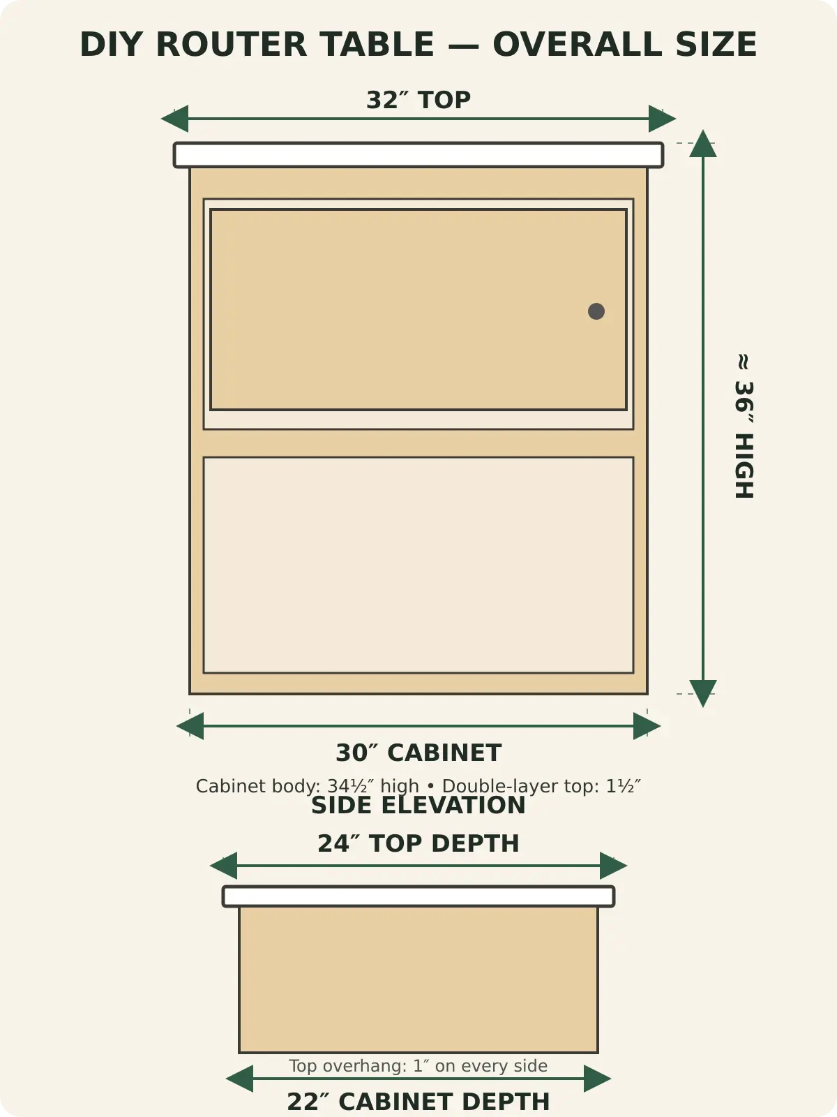
The cabinet body is exactly 34½ inches high. Adding the 1½-inch double-layer top produces a nominal 36-inch work height before laminate, edge treatment or adjustable feet. The 32-by-24-inch top overhangs the 30-by-22-inch cabinet by one inch on all four sides.
The side panels are 21½ inches deep. A ½-inch back panel brings the cabinet to a total depth of 22 inches. Inside, the 28½-inch-wide divider separates an upper router compartment from an open lower storage bay. The divider’s top sits 16 inches above the cabinet bottom, leaving a lower clear opening of about 14½ inches and generous space above for a compatible router.
Why This Router Table Design Works
The design intentionally avoids complicated drawers and a router lift. That keeps the first build understandable while preserving the features that affect accuracy and safety most.
- Double-layer MDF top: The 1½-inch core resists sagging and provides a broad, flat surface. A smooth laminate or melamine wear face reduces friction.
- Replaceable insert plate: The router mounts to the plate rather than directly to the MDF. You can remove the complete assembly for maintenance or future upgrades.
- Rigid cabinet: Plywood sides, a full back, divider and top stretchers resist racking and damp vibration.
- Accessible compartment: The front door gives access to the router while helping contain chips. Vent openings supply cooling air.
- Split fence: Two movable faces close the gap around different bit sizes while the rear dust hood collects debris.
- Open lower shelf: Router bits, push blocks and setup tools stay near the machine without crowding the tabletop.
For other shop-made accuracy aids, explore these 15 essential router jigs and the broader collection of time-saving woodworking jigs.
Materials and Hardware
Sheet Goods and Wood
- One 4′ × 8′ sheet of ¾-inch cabinet-grade plywood
- One 48″ × 48″ panel of ¾-inch MDF for the two top layers
- One 30″ × 34½″ piece of ½-inch plywood for the back
- High-pressure laminate or another durable, smooth top surface
- Approximately 9 linear feet of hardwood edging or iron-on edge banding
- Four 10-inch hardwood cleats, approximately 1½″ × 1½″
Router-Table Hardware
- One compatible router insert plate, nominally 9¼″ × 11¾″ × ⅜″
- Plate-leveling hardware or eight compatible leveling screws and threaded inserts
- Router mounting screws specified by the router/plate manufacturer
- Commercial paddle-style safety switch rated for the router
- One 2½-inch dust port for the fence hood
- Optional second cabinet dust port if supported by the extraction system
- Two featherboards, push blocks and a compatible clear bit guard
- Two edge clamps for the fence, or compatible T-track and knob hardware
General Hardware
- 1¼-inch coarse-thread pocket-hole screws or appropriate predrilled cabinet screws
- 1-inch screws for the ½-inch back
- 1¼-inch screws for laminating the top from the underside
- Three door hinges, a magnetic catch and one handle
- Wood glue, construction-safe contact adhesive for laminate and optional edge-band adhesive
- Four non-slip leveling feet, optional
The common Kreg phenolic plate is officially listed at 9¼ by 11¾ inches and ⅜ inch thick, which is why this plan uses those nominal measurements. Other brands use different footprints, corner radii and mounting patterns. Review the manufacturer’s insert-plate specifications and measure the plate in your hands.
Complete Router Table Cut List
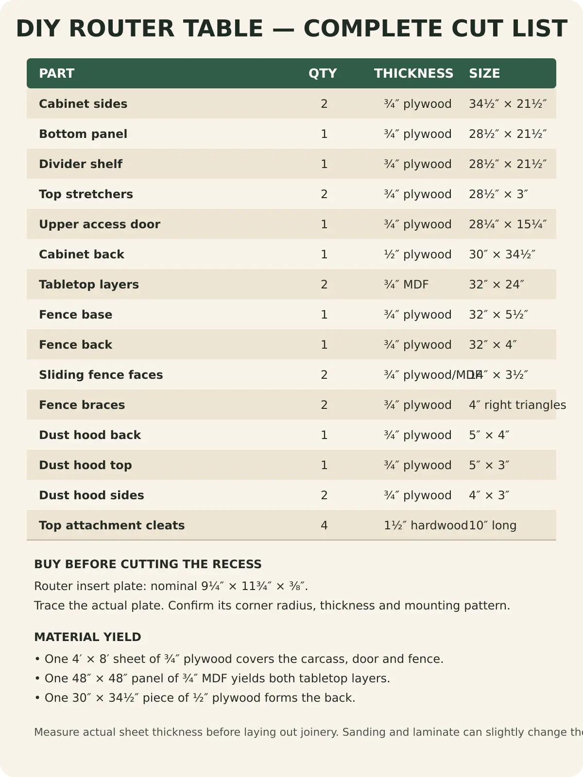
| Part | Qty. | Material | Finished size |
|---|---|---|---|
| Cabinet sides | 2 | ¾″ plywood | 34½″ × 21½″ |
| Bottom | 1 | ¾″ plywood | 28½″ × 21½″ |
| Divider | 1 | ¾″ plywood | 28½″ × 21½″ |
| Top stretchers | 2 | ¾″ plywood | 28½″ × 3″ |
| Upper door | 1 | ¾″ plywood | 28¼″ × 15¼″ |
| Back | 1 | ½″ plywood | 30″ × 34½″ |
| Tabletop layers | 2 | ¾″ MDF | 32″ × 24″ |
| Fence base | 1 | ¾″ plywood | 32″ × 5½″ |
| Fence back | 1 | ¾″ plywood | 32″ × 4″ |
| Sliding fence faces | 2 | ¾″ plywood/MDF | 14″ × 3½″ |
| Fence braces | 2 | ¾″ plywood | 4″ right triangles |
| Dust-hood back | 1 | ¾″ plywood | 5″ × 4″ |
| Dust-hood top | 1 | ¾″ plywood | 5″ × 3″ |
| Dust-hood sides | 2 | ¾″ plywood | 4″ × 3″ |
Tools Needed
- Track saw or circular saw with a straight cutting guide
- Handheld plunge or fixed-base router and a straight bit
- Jigsaw for roughing out the insert opening
- Drill/driver, countersink and hole saw sized for the dust port
- Pocket-hole jig or suitable predrilling setup
- Combination square, long straightedge, tape measure and marking knife/pencil
- Clamps, including enough to laminate the full tabletop
- Random-orbit sander and 120-, 150- and 180-grit abrasives
- Flush-trim bit and a template made for the actual insert plate
- Personal protective equipment required by each tool manufacturer
If your tool collection is still growing, compare this list with the free woodworking plans for beginners before buying specialty equipment for one project.
Insert Plate and Top Layout
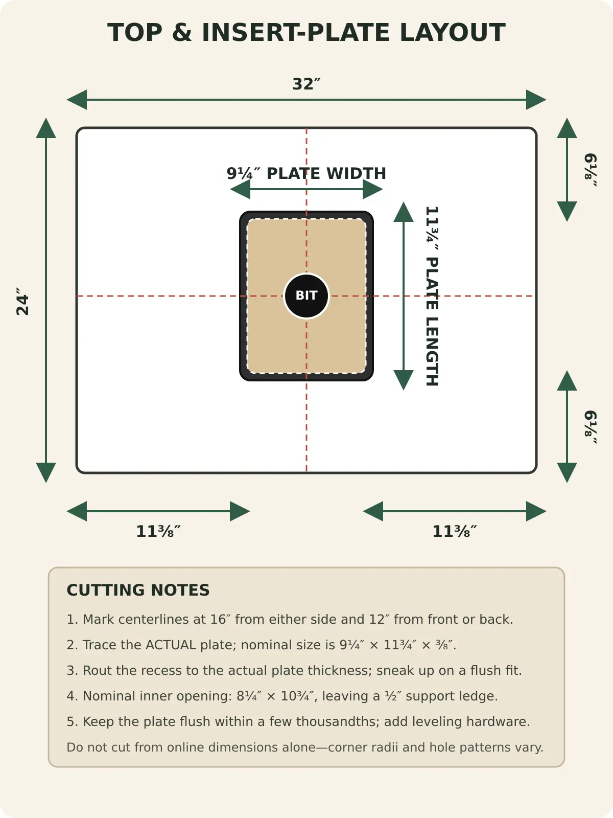
Mark one centerline 16 inches from either side and a second 12 inches from the front or back. Center the actual plate where the lines cross. A nominal 9¼-by-11¾-inch plate leaves 11⅜ inches of tabletop on both sides and 6⅛ inches at both ends.
The inner opening shown is 8¼ by 10¾ inches, which leaves a ½-inch ledge around the nominal plate. Treat that opening only as a starting point. Confirm that the ledge supports the plate’s full perimeter without obstructing the router motor, height controls, lift mechanism or mounting hardware.
How to Build the DIY Router Table
Step 1: Cut and Label Every Part
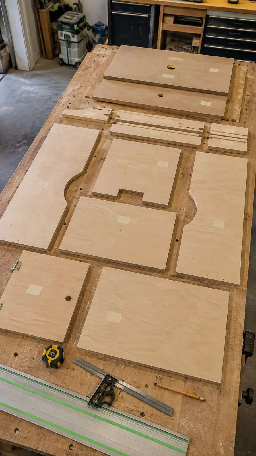
Break down the ¾-inch plywood using a track saw or a circular saw against a verified straight guide. Cut both side panels together from the same rip so they remain identical. Then cut the bottom, divider, top stretchers and door. Finish with the narrower fence parts and dust-hood pieces.
Label each piece with removable masking tape. Mark the front edge and the preferred visible face. Sheet goods are not always exactly ¾ inch thick, so measure the actual material before drilling pocket holes or laying out any dado. Check every panel for square by comparing diagonals or using a reliable framing square.
Step 2: Build the Double-Layer Tabletop
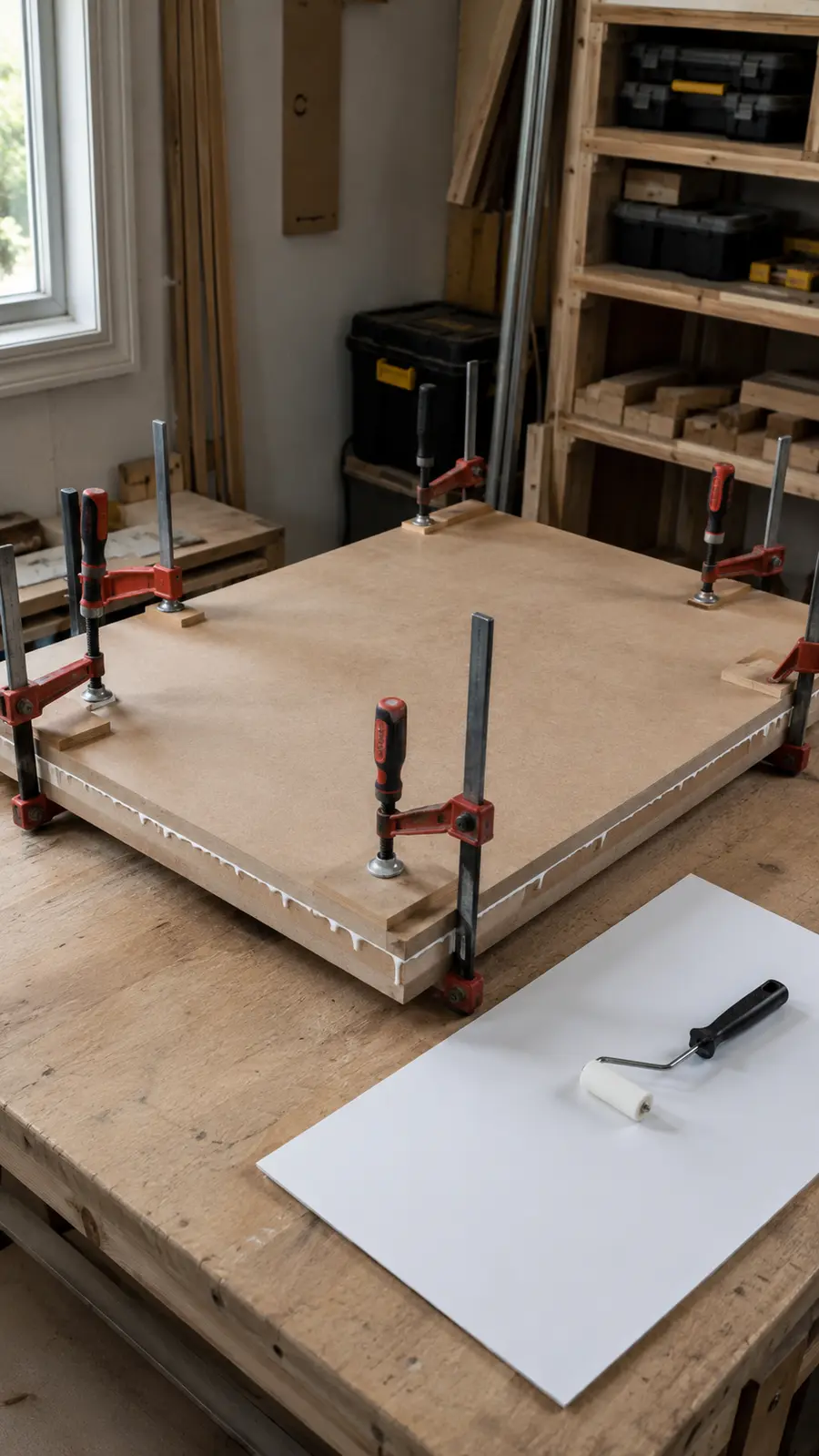
Dry-align the two 32-by-24-inch MDF panels and confirm that their edges match. Spread an even film of glue, bring the panels together and secure them with clamps and cauls. Drive 1¼-inch screws from the underside only, keeping all screws well outside the future plate opening and fence-hardware zones.
Once the glue cures, trim any mismatch with a flush-trim bit or straightedge. Apply the smooth wear surface according to its adhesive manufacturer’s instructions, then trim the laminate flush. Seal or edge-band every exposed MDF edge so moisture cannot swell the core. Keep the underside identifiable throughout the build.
Step 3: Cut the Insert-Plate Recess
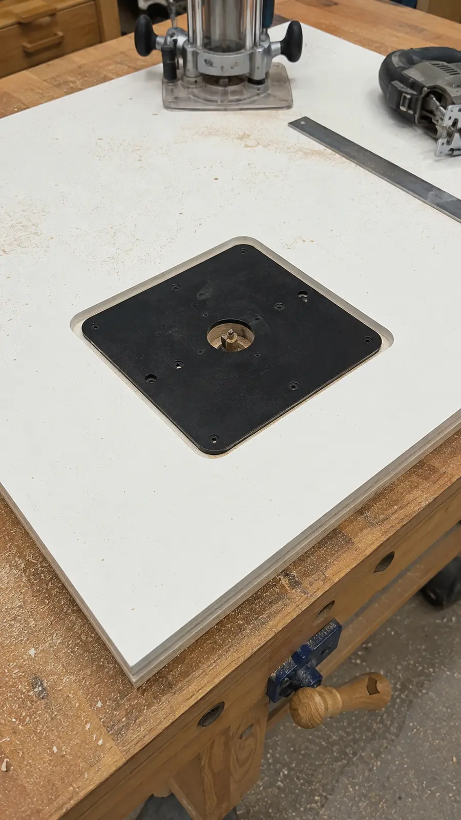
Lay out the crossing centerlines, place the actual plate on the tabletop and trace it. Make a precise template that matches the plate’s outline and corner radius. Secure the template so it cannot move. Rout the recess in shallow passes until it is just deep enough for the plate to sit flush with the surface.
Rough-cut the smaller inner opening with a jigsaw, staying inside the line. Finish it to the nominal 8¼-by-10¾-inch opening only after checking underside clearance. Install commercial levelers or threaded inserts where they fully support the plate. The plate should lift out without binding but must not slide during use.
Step 4: Assemble the Cabinet Carcass
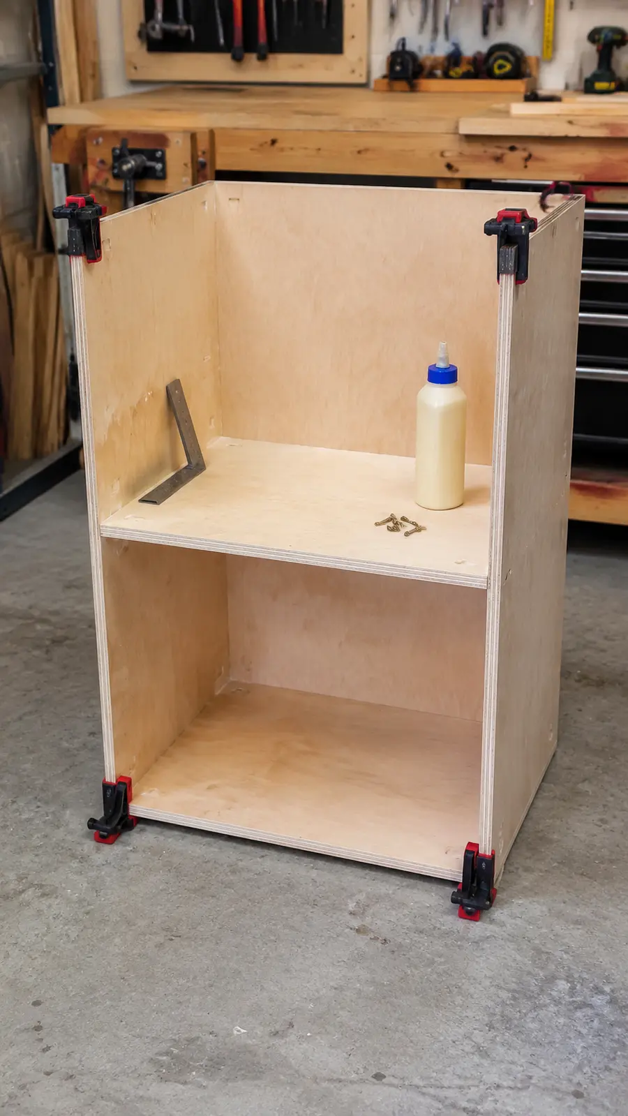
Place the two sides with their inside faces upward. The bottom panel fits between them with its lower face flush with the side-panel bottoms. Position the divider so its top face is exactly 16 inches above the cabinet bottom. That means the divider’s lower face is 15¼ inches above the bottom edge.
Use glue and 1¼-inch pocket-hole screws from the hidden faces, or use suitable cabinet screws through carefully predrilled and countersunk side panels. Clamp the assembly to a square before tightening. Add the two 28½-by-3-inch top stretchers between the sides, flush with the top edges—one at the front and one at the rear.
Step 5: Add the Back, Dust Port and Ventilation
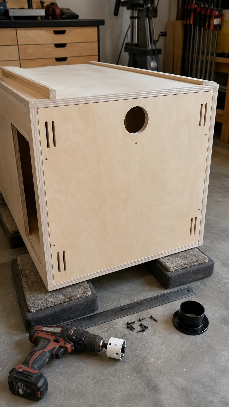
Square the cabinet by comparing its diagonals, then fasten the 30-by-34½-inch back with glue and 1-inch screws. Keep the back flush with the side edges. The ½-inch panel completes the 22-inch cabinet depth and locks the box square.
Cut a 2½-inch port opening high in the router compartment where the hose will not interfere with the motor or height adjustment. Add ventilation slots or screened openings on opposite sides of the upper compartment. Dust collection needs replacement air, and the router needs manufacturer-specified cooling clearance. Never seal the motor inside an airtight box.
Step 6: Fit the Door and External Safety Switch
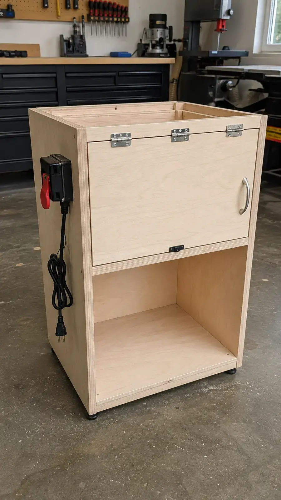
The upper opening is approximately 28½ inches wide by 15½ inches high. The 28¼-by-15¼-inch inset door creates a ⅛-inch reveal on all four sides. Test the fit before finishing, then install three hinges, a magnetic catch and a simple handle. The door must open freely without rubbing the tabletop or switch.
Mount the rated paddle switch in a position you can reach without leaning toward the bit. Follow the switch and router manuals for connection. Keep factory cords away from the router collet, height mechanism, dust hose, sharp edges and door hinges. Do not alter cords or make permanent electrical connections as part of this wooden plan.
Step 7: Attach and Center the Tabletop
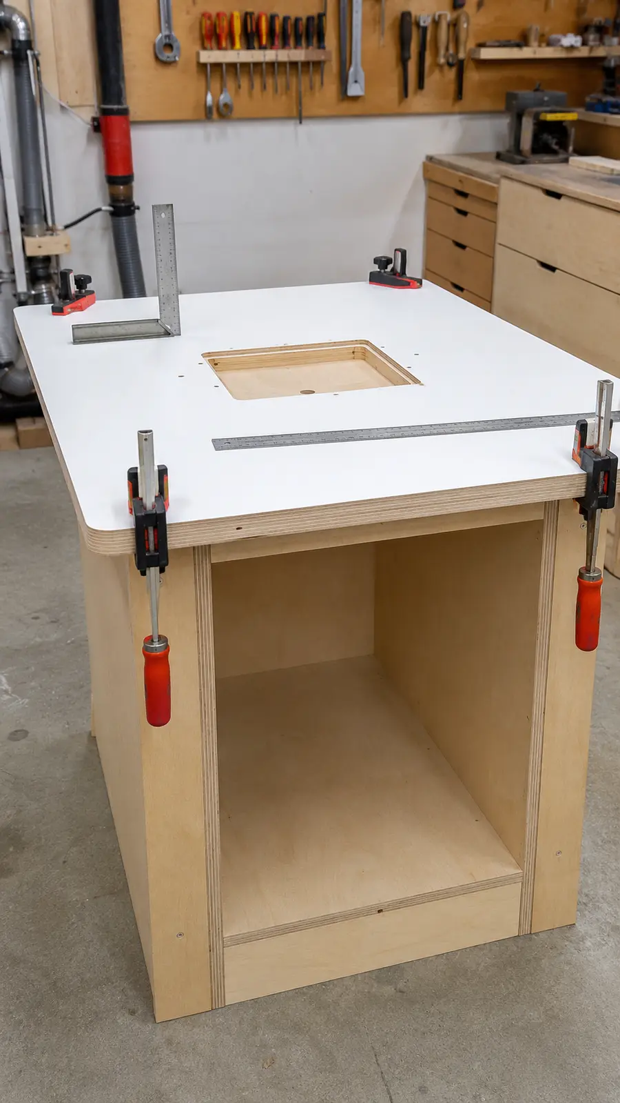
Set the top on the cabinet and measure the overhang at all four sides. When centered, it should be one inch at the left, right, front and back. Clamp it without bowing the surface. Fasten upward through the front and rear stretchers and the four hardwood cleats with screws that cannot reach the top face.
Do not glue the tabletop permanently to the cabinet. Screws make the top removable if it is ever damaged or replaced with a different plate system. Confirm that every screw lies clear of the recess, levelers and router.
Step 8: Build the Adjustable Fence and Dust Hood
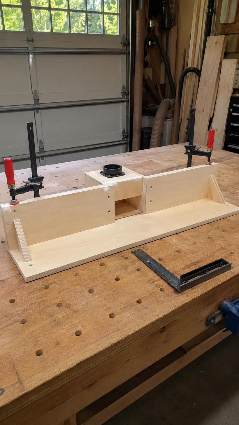
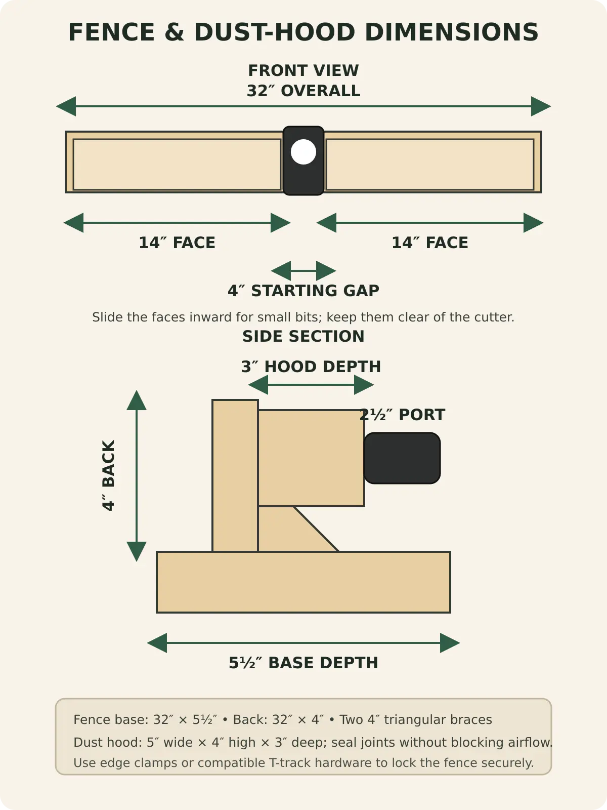
Join the 32-by-4-inch fence back at 90 degrees to the 32-by-5½-inch base. Add the two 4-inch triangular braces behind it while keeping the front face straight. Build the centered dust hood from the 5-by-4-inch back, 5-by-3-inch top and two 4-by-3-inch sides, then install the 2½-inch port.
Mount the two 14-by-3½-inch faces so they can slide horizontally. A four-inch starting gap leaves room for common bits, but the faces should close farther for smaller cutters while remaining safely clear of the spinning bit. The fence can lock with clamps at both table edges. If you add T-track, use compatible hardware and place it where it cannot weaken the plate recess.
Step 9: Mount the Router to the Insert Plate
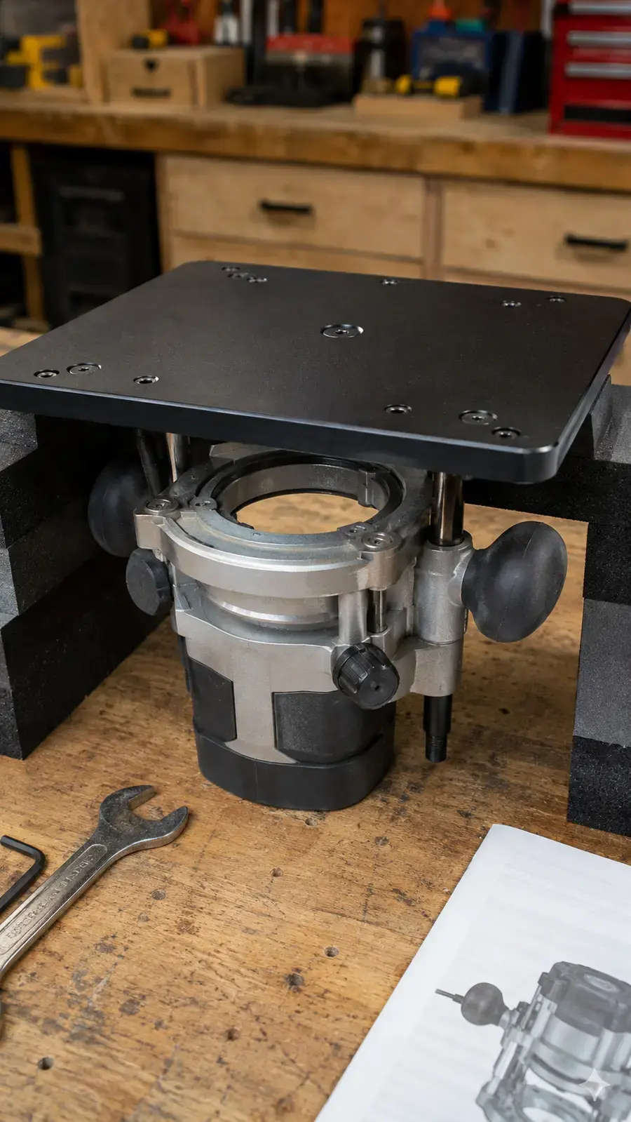
Unplug the router and remove the bit. Place the plate upside down on padded blocks so it cannot be scratched. Center the router’s collet opening beneath the plate ring and mark only the holes required by the manufacturer. Predrill or countersink exactly as the plate instructions specify.
Use correctly sized machine screws that fully engage the router base without bottoming out. Do not substitute long screws that can enter the motor housing. Recheck that the router controls, collet lock and height adjustment remain accessible before lifting the complete plate assembly into the table.
Step 10: Level the Plate and Square the Fence
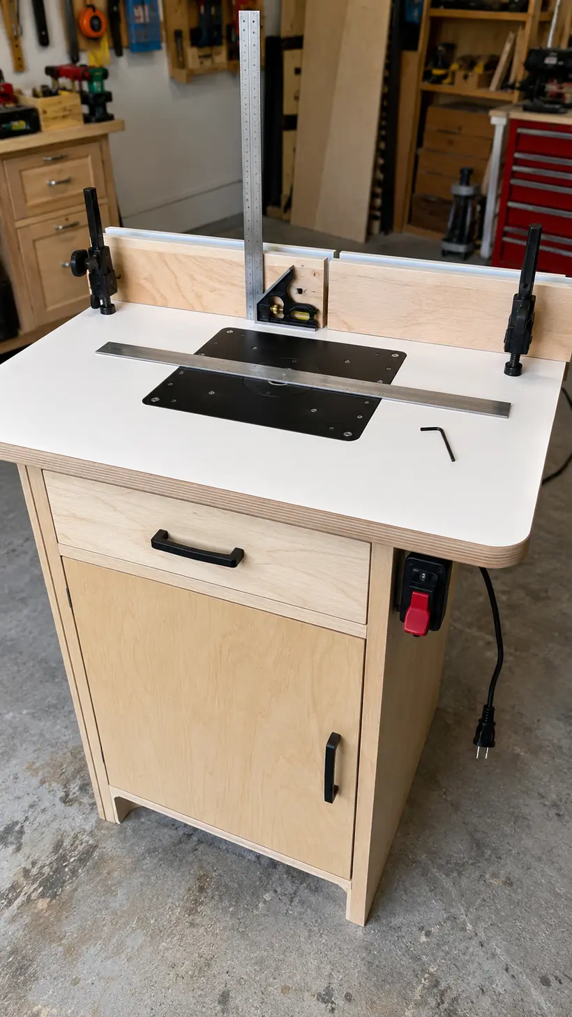
Lower the plate assembly into the recess and adjust the levelers a little at a time. Check front-to-back, side-to-side and diagonally with a reliable straightedge. A workpiece should not catch on the plate edge, and the plate must not rock under pressure.
Clamp the fence behind the bit opening and verify that both split faces lie in one plane. For bearing-guided edge profiles, the fence position may be less critical, but it still must remain locked. For grooves and dados, measure from the cutter to the fence and test on scrap before touching the project part.
Step 11: Complete the Safety and Dust-Control Test
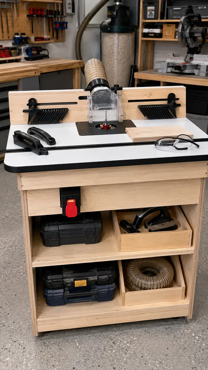
With the router still unplugged, rotate the collet by hand to confirm the bit path is clear. Install the smallest compatible insert ring, set the split faces close to the bit without contact, connect the fence hose, position the guard and adjust featherboards for the test stock. Confirm that the paddle switch is reachable and that the router compartment door closes without crushing any cable or hose.
Connect power according to the product manuals, stand clear and start the router without stock touching the bit. Watch and listen for vibration, plate movement, rubbing or unusual noise. Shut it off immediately if anything seems wrong. After a clean no-load test, make one light pass on a straight piece of scrap, feeding in the manufacturer-approved direction.
How to Calibrate the Router Table
- Check plate flushness: Move a straightedge across every edge of the plate. Adjust until it neither catches nor rocks.
- Align fence faces: Span the left and right faces with a straightedge. Shim or adjust them until they form one plane.
- Set the bit height: Disconnect power, set the cutter with a setup block or gauge, then lock the router adjustment.
- Set fence depth: Measure from the cutting edge, not the bit center. Lock both ends of the fence.
- Test on scrap: Use the same thickness and species as the project stock. Check the result before routing finished parts.
Store setup blocks, collet wrenches and frequently used push tools on the lower shelf, but keep loose objects out of the upper router bay. A nearby power-tool organizer with a charging station and these DIY tool-storage ideas can keep the rest of the work area clear.
For a free starting point, use the small woodworking shop setup guide. If another stationary tool needs a dedicated home, compare this cabinet with the miter saw station plans for small workshops.
Optional Router Table Upgrades
Add Locking Casters
Mobility can help in a shared garage, but caster height changes the work height and raises the center of gravity. Measure the actual installed height of the chosen casters and shorten the cabinet sides by the same amount. Use four properly rated double-locking casters and confirm that the table cannot roll or swivel during use.
Add a Miter Slot or T-Track
A combination track can accept some featherboards and accessories. Position it only after the plate recess is complete, and keep fasteners clear of the router compartment. A miter slot is not required for ordinary edge routing, so do not add one merely because commercial tops include it.
Add a Router Lift
A lift makes above-table height changes easier, but it may weigh more and require a particular plate opening. Verify the lift dimensions and top-support requirements before modifying the recess. Do not assume every lift fits a nominal 9¼-by-11¾-inch opening.
Add Drawers Below
The open lower bay can accept a removable drawer unit later. Keep heavy accessories low and avoid letting drawers interfere with leveling feet, casters or the switch cord. Building the open version first also shows which router accessories actually deserve dedicated storage.
If saving floor space matters more than machine storage, a folding wall-mounted workbench can preserve a separate assembly surface near the router table.
Common Router Table Building Mistakes
Cutting the Recess Before Buying the Plate
Nominal dimensions do not describe the corner radius, screw positions or tolerance of every plate. Trace the real part and make a test recess in scrap if possible.
Letting the Plate Sit Proud or Low
Even a small lip can catch a workpiece and change cutting depth. Use leveling hardware and check every edge with a straightedge.
Building an Airtight Router Box
The router requires cooling air, and dust extraction requires incoming air. Follow the machine and extractor requirements; do not sacrifice ventilation merely to contain chips.
Using a Light-Duty Switch
The switch must be specifically rated for the router load and application. A large red paddle improves access, but its electrical rating and manufacturer-approved connection are what matter.
Making the Fence Decorative Instead of Straight
A twisted fence ruins repeatability. Assemble it against a flat reference, check that the faces share one plane and lock both ends before every cut.
Ignoring Workpiece Support
The 32-inch top suits many parts, not every board. Support long stock independently without lifting it away from the tabletop or forcing the operator into an awkward path.
Frequently Asked Questions
What is the best height for a DIY router table?
About 36 inches is a practical general-purpose height for many adults, which is why this plan uses it. Comfort varies with body height and task. If you change the height or add casters, recalculate the cabinet before cutting rather than stacking blocks under a finished machine.
Can I use plywood instead of MDF for the top?
Yes, if the plywood is flat and well supported. MDF is popular because it is uniformly flat and stable, while plywood holds screws better and tolerates moisture somewhat better. A double-layer plywood top can work, but check it carefully for bow and voids.
Can I mount the router directly under the tabletop?
A direct mount is possible with some designs, but it reduces convenient access and makes the top opening harder to service. A compatible insert plate provides a controlled mounting surface and makes the router easier to remove.
Does the fence have to be perfectly parallel to the table edge?
Not for most router-table operations. The important relationship is between the cutter and the fence faces, and both fence ends must be locked. If a miter slot or guided accessory is used, follow its alignment requirements.
Which direction should I feed stock on a router table?
With a conventional setup and the fence behind the bit, stock is usually fed from right to left so it moves against cutter rotation. Follow the router and router-table manuals because unusual operations can require different procedures. Do not climb-cut simply to avoid tear-out.
Do I need two dust ports?
No. Start with the fence port, where many chips are produced. A second port in the cabinet can improve collection only when the extractor supplies adequate airflow and the enclosure retains sufficient cooling-air openings.
Can this router table be stored outdoors?
No. MDF, plywood, electrical tools and precision plates belong in a dry indoor workshop. Humidity can swell the top, corrode hardware and affect accuracy even when the exterior has been finished.
Final Thoughts
A useful DIY router table does not need a complicated lift, ten drawers or a massive footprint. It needs a flat top, a properly supported insert plate, a straight fence, stable construction, accessible power control and dust management that does not starve the motor of cooling air.
Cut the cabinet parts accurately, trace the plate you actually own and spend extra time leveling the finished surface. Then calibrate on scrap and take light passes. Those careful setup habits will matter far more than decorative details—and they will make this compact router table one of the most useful stations in your workshop.